Thermaltake Toughpower GF3 1350W ATX v3.0 Power Supply Review
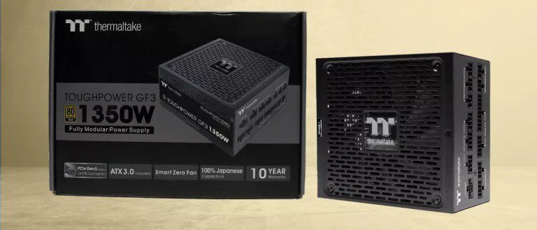
The Thermaltake Toughpower GF3 1350W is a high-performance power supply.
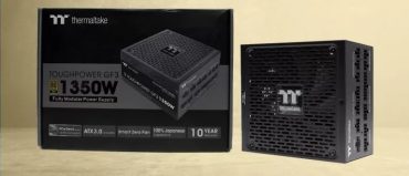
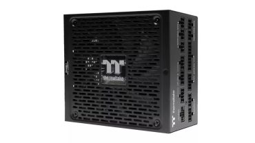
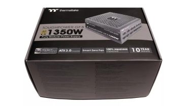
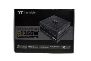
The Thermaltake Toughpower GF3 1350W achieves high overall performance, making it one of the best PSUs you can buy. On top of that, this PSU is ATX v3.0 and PCIe 5.0 ready, so it comes with a 12VHPWR connector out of the box, supporting NVIDIA’s newest GPUs without the need for adapters.
Thermaltake released many new PSUs recently, including the GF3 line, which covers the mid and higher Wattage ratings, from 750W to 1650W. The strongest GF3 models, with 1350W and 1650W, are by High Power, while all others are made by Channel Well Technology (CWT). We will look at the 1350W model in this review and stress it to the max during the new transient response tests that the ATX v3.0 spec requires, including a 2700W load test.
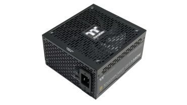
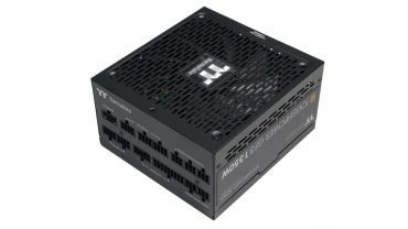
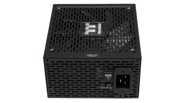
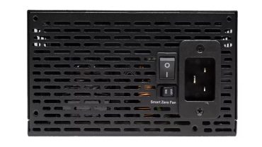
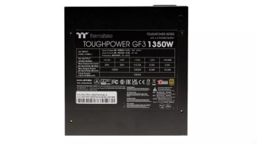
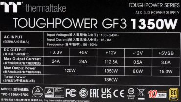
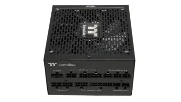
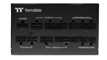
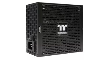
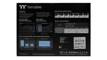
The GF3 1350 is certified as 80 PLUS Gold, but in the Cybenetics scheme, it scored a Platinum rating. It also has a Cybenetics Standard noise rating, which shows that this is not a quiet PSU.
Because of its modest 160mm depth and 1350W maximum power, we didn’t expect it to be quiet, but an over 40 dBA average noise output is too high. Thermaltake should go with a larger PCB, allowing for better airflow; thus, the cooling fan wouldn’t have to work over hours at high speeds to handle the heat load.

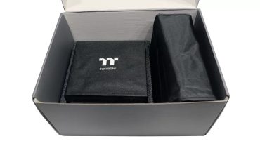
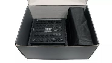


Specifications of Thermaltake Toughpower GF3 1350W
| Manufacturer (OEM) | High Power |
| Max. DC Output | 1350W |
| Efficiency | 80 PLUS Gold, Cybenetics Platinum (89-91%) |
| Noise | Cybenetics Standard (40-45 dB[A]) |
| Modular | ✓ (fully) |
| Intel C6/C7 Power State Support | ✓ |
| Operating Temperature (Continuous Full Load) | 0 – 40°C |
| Over Voltage Protection | ✓ |
| Under Voltage Protection | ✓ |
| Over Power Protection | ✓ |
| Over Current (+12V) Protection | ✓ |
| Over Temperature Protection | ✓ |
| Short Circuit Protection | ✓ |
| Surge Protection | ✓ |
| Inrush Current Protection | ✓ |
| Fan Failure Protection | ✗ |
| No Load Operation | ✓ |
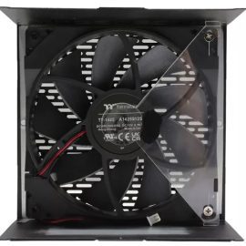
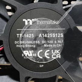
| Cooling | 140mm Hydraulic Bearing Fan [TT-1425 (A1425S12S-2)] |
| Semi-Passive Operation | ✓ (selectable) |
| Dimensions (W x H x D) | 150 x 85 x 160mm |
| Weight | 1.84 kg (4.06 lb) |
| Form Factor | ATX12V v3.0, EPS 2.92 |
| Alternative Low Power Mode (ALPM) compatible | ✓ |
| Warranty | 10 Years |
Power Specifications of Thermaltake Toughpower GF3 1350W
| Rail | Row 0 – Cell 1 | 3.3V | 5V | 12V | 5VSB | -12V |
| Max. Power | Amps | 24 | 24 | 112.5 | 3 | 0.5 |
| Row 2 – Cell 0 | Watts | Row 2 – Cell 2 | 120 | 1350 | 15 | 6 |
| Total Max. Power (W) | Row 3 – Cell 1 | Row 3 – Cell 2 | 1350 | Row 3 – Cell 4 | Row 3 – Cell 5 | Row 3 – Cell 6 |
Cables & Connectors for Thermaltake Toughpower GF3 1350W
| Description | Cable Count | Connector Count (Total) | Gauge | In Cable Capacitors |
|---|---|---|---|---|
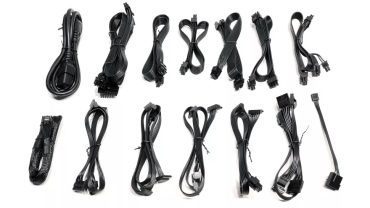
| ATX connector 20+4 pin (600mm) | 1 | 1 | 18AWG | No |
| 8 pin EPS12V (700mm) | 1 | 1 | 16AWG | No |
| 4+4 pin EPS12V (700mm) | 1 | 1 | 16AWG | No |
| 6+2 pin PCIe (500mm+150mm) | 3 | 6 | 16-18AWG | No |
| 12+4 pin PCIe (500mm) (600W) | 1 | 1 | 16-24AWG | No |
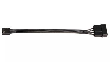
| SATA (500mm+150mm+150mm) | 4 | 12 | 18AWG | No |
| 4-pin Molex (500mm+150mm+150mm+150mm) | 1 | 4 | 18AWG | No |
| FDD Adapter (150mm) | 1 | 1 | 22AWG | No |
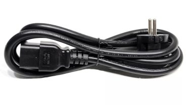
| AC Power Cord (1390mm) – C19 coupler | 1 | 1 | 16AWG | – |
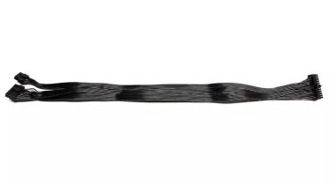
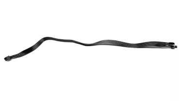
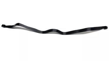
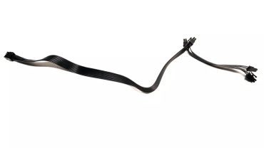
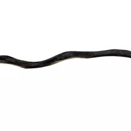
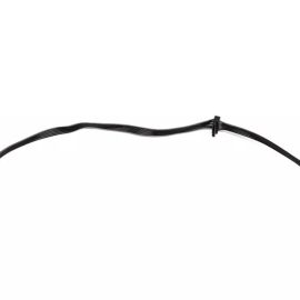
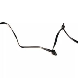
There are plenty of connectors installed on long cables. Besides the 600W 12VHPWR, we also find six PCIe 6+2 on three cables. The number of peripheral connectors is also high. Finally, the PSU uses a heavy-duty power cord.
Component Analysis of Thermaltake Toughpower GF3 1350W
We strongly encourage you to have a look at our PSUs 101 article, which provides valuable information about PSUs and their operation, allowing you to better understand the components we’re about to discuss.
| General Data | – |
| Manufacturer (OEM) | High Power |
| PCB Type | Double Sided |
| Primary Side | – |
| Transient Filter | 4x Y caps, 2x X caps, 2x CM chokes, 1x MOV, 1x MPS HF81 (Discharge IC) |
| Inrush Protection | 1x NTC Thermistor SCK-057 (5 Ohm) & Relay |
| Bridge Rectifier(s) | 2x GBJ5006 (600V, 50A @ 100°C) |
| APFC MOSFETs | 2x Infineon IPW60R060P7 (600V, 30A @ 100°C, Rds(on): 0.06Ohm) |
| APFC Boost Diode | 1x Toshiba TRS12E65F (650V, 12A) |
| Bulk Cap(s) | 2x Rubycon (420V, 680uF each or 1360uF combined, 2,000h @ 105°C, MXE) |
| Main Switchers | 2x Infineon IPP60R060P7 (600V, 30A @ 100°C, Rds(on): 0.06Ohm) |
| APFC Controller | Infineon ICE3PCS01G |
| Resonant Controller | Champion CU6901V |
| Topology | Primary side: APFC, Half-Bridge & LLC converter Secondary side: Synchronous Rectification & DC-DC converters |
| Secondary Side | – |
| +12V MOSFETs | 8x Infineon BSC010N04LS (40V, 178A @ 100°C, Rds(on): 1mOhm) |
| 5V & 3.3V | DC-DC Converters: 8x Infineon BSC0906NS (30V, 40A @ 100°C, Rds(on): 4.5mOhm) PWM Controller(s): ANPEC APW7159C |
| Filtering Capacitors | Electrolytic: 5x Rubycon (3-6,000h @ 105°C, YXG), 1x Nichicon (4-10,000h @ 105°C, HE), 2x Rubycon (6-10,000h @ 105°C, ZLH), 2x Rubycon (4-10,000h @ 105°C, YXJ) Polymer: 20x FPCAP, 4x Nippon Chemi-Con |
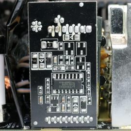
| Supervisor IC | Weltrend WT7527RA (OCP, OVP, UVP, SCP, PG) |
| Fan Controller | STCmicro STC15W408AS |
| Fan Model | Thermaltake TT-1425 (A1425S12S) (140mm, 12V, 0.70A, Hydraulic Bearing Fan) |
| 5VSB Circuit | – |
| Rectifier(s) | 1x Infineon IPN70R1K4P7S (700V, 2.5A @ 100°C, Rds(on): 1.4Ohm) & 1x PFC P10V45SP SBR (45V, 10A) |
| Standby PWM Controller | Si-Trend SI8016HSP8 |
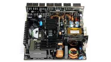
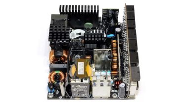
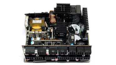
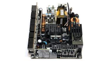
The PCB is small for a 1350W monster, so it is over-populated with parts, and the heat sinks are small. With a larger PCB, there would be more space between parts, allowing for better airflow, and there wouldn’t be a tight limitation on the footprint of the heat sinks. The build quality is high, with Japanese caps used everywhere, along with good FETs. Moreover, the soldering quality is good.
The PCB is small for a 1350W monster, so it is over-populated with parts, and the heat sinks are small. With a larger PCB, there would be more space between parts, allowing for better airflow, and there wouldn’t be a tight limitation on the footprint of the heat sinks. The build quality is high, with Japanese caps used everywhere, along with good FETs. Moreover, the soldering quality is good.
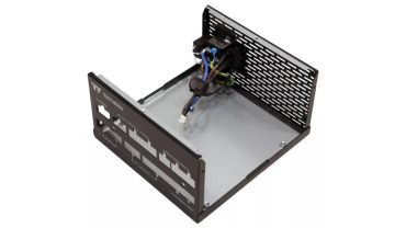
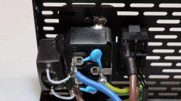
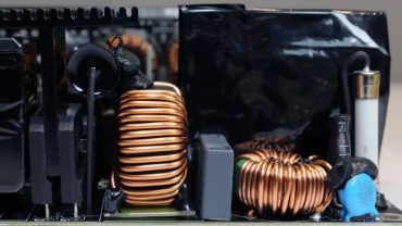
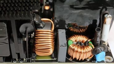
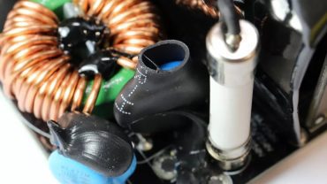
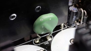
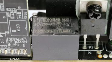
The transient/EMI filter has all the required parts. There is also a discharge IC to restrict energy losses on the resistor bleeder, used to drain the X caps once the PSU is shut down. We find an MOV and an NTC thermistor and bypass relay combo for surge and inrush protection.
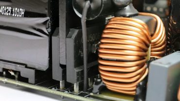
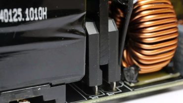
The pair of bridge rectifiers can handle up to 100A in total. This is insane!
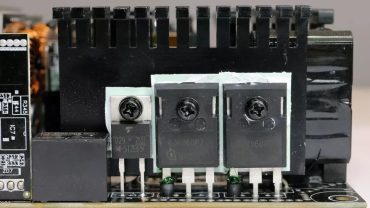
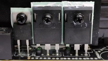
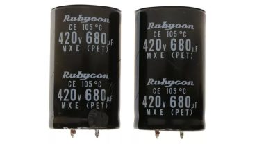
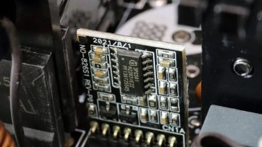
The APFC converter uses two Infineon FETs and a single Toshiba boost diode. There are two bulk caps with 1360uF combined capacity, which is enough for this PSU’s needs. The APFC controller is an Infineon ICE3PCS01G IC.
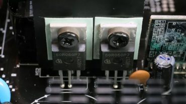
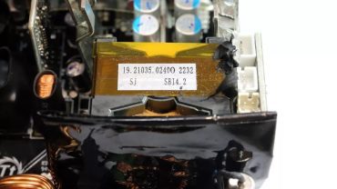
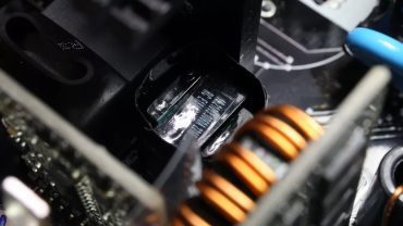
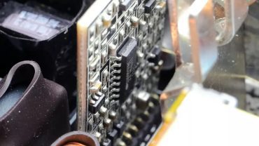
The main Infineon FETs are installed in a half-bridge topology. We usually find a full-bridge topology in high-capacity units because it can handle high power levels without excess energy losses.
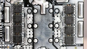
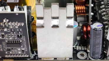
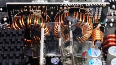
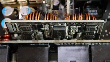
Eight Infineon FETs regulate the 12V rail. They are installed on the PCB’s solder side. Lastly, two DC-DC converters generate the minor rails.
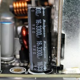
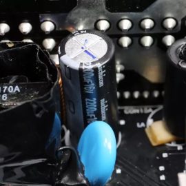
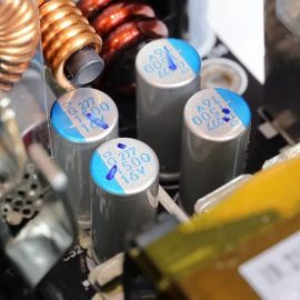
All filtering caps are by Japanese manufacturers and belong to good lines. Lots of polymer caps are also used.
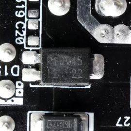
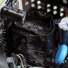
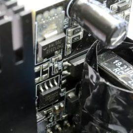
The standby PWM controller is a Si-Trend SI8016HSP8. On the primary side of the 5VSB circuit, we find a FET, and on the secondary side, an SBR.
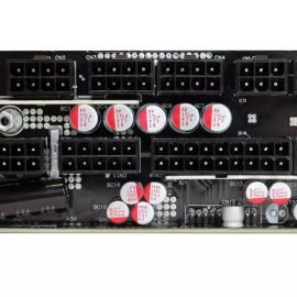
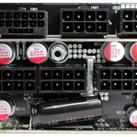
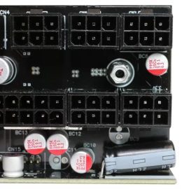
The modular hosts polymer and electrolytic caps, for ripple filtering.
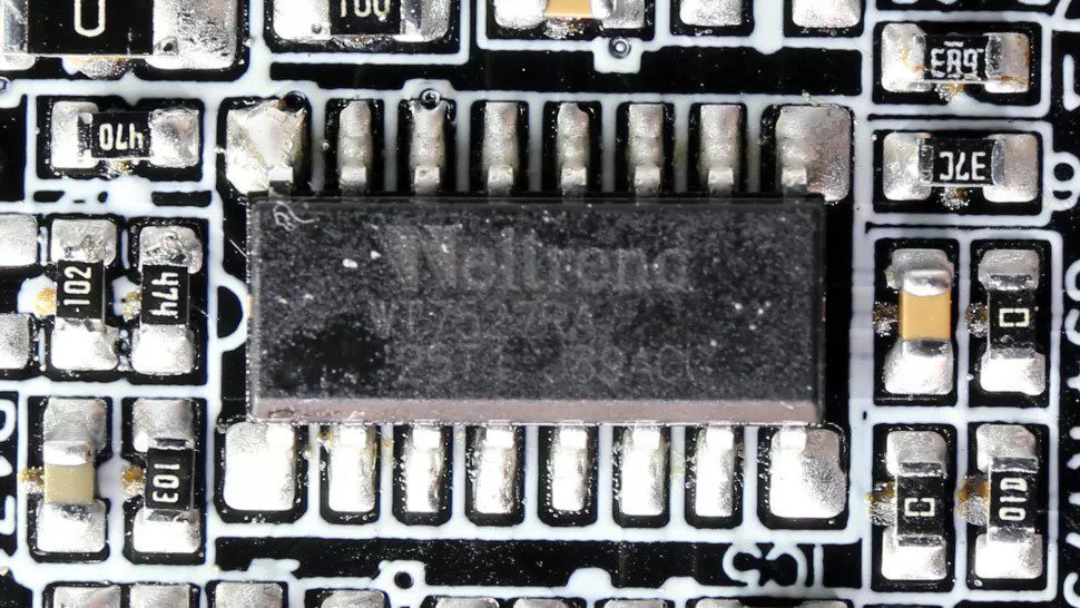
The main supervisor IC is a Weltrend WT7527RA.
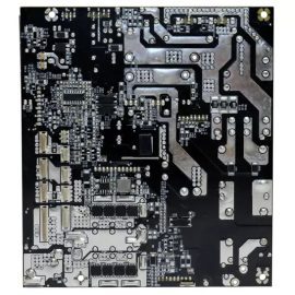
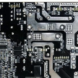
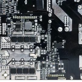
Soldering quality is high.
